


Cabling and connector industry
A P.A. or lightning system cannot run properly without appropriate cabling. Indeed each cable has a specific function. One could say it is only a piece of metal through which the electrical signal goes through. Unfortunately, it’s not all that simple!
The goal of this topic is to set out the major features of a cable, without going into incomprehensible demonstrations and mathematical formulae.
Some electricians or electronic engineers will probably find it incomplete or too simple, but my purpose is to give a simpler explanation on this subject and certainly not to replace specialized books.
1. As a rule...
A cable is made up of one or several conductors. Each conductor is coated with an insulator. Those conductors are also made up of one or several metal strands.
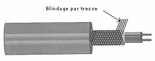
The conductors may also be covered with a metal braid (or an aluminium strip), offering a practical solution for matching signals against interferences. That is what we call a shielded cable.
Those conductors have their own features and can be subjected to different effects, which are described below.
1.1 Resistive effect
Each conductor has a given resistance that depends on several parameters:
- Influence of the conductor type
Depending on the metal or alloy used for the conductor, its resistance will vary.
Some materials have more free electrons per unit volume than others. If the number of free electrons is higher, the material will be a better conductor, and it will be easier for the current to get through.
Let’s simplify: the more carrier charges a conductor contains, the less the charge of each conductor is in comparison to the total energy.
Consequently, the amount of energy converted into heat - because of multiple collisions with metal atoms - is reduced.
For example, a silver conductor is less resistive than a copper conductor with a same section.
The resistivity of a conductor corresponds to the resistance of a one-meter conductor with a one square meter section.
This phenomenon can be explained by Pouillet’s law:
This law sets down the following relation:
The resistance of a conductor is directly proportional to its resistivity () and to its length (L) ; and is inversely proportional to this conductor section (S).
R = x L/ S
R is the electrical resistance of the conductor in ohms
is the matter resistivity in mm²/ m
L is the conductor length in m
S is the conductor section in mm²
Note: Depending on its diameter, the cable section is calculated as follow:
S=x d²/4
Depending on its radius, the cable section is calculated as follow:
S= x r²
Examples of values in mm²/m at 20°C:
Copper 0.017
Silver 0.016
Alu 0.028
Iron 0.1
- Influence of the temperature
In most theoretical cases, we consider that the temperature remains constant at 20°C. But this is rarely the case.
In fact, we observe that conductor resistance increases with the temperature. Nevertheless, some materials offer a resistance that decreases with the temperature (Superconductors); they will not be tackled in this topic.
This relation is explained by Mathiessen’s law, which can be expressed as follow:
Rt = R (1 + α t)
Rt is the resistance value at temperature t
R is the resistance value at 0°C
α is the conductor temperature coefficient
t is the temperature difference in centigrade degrees
Some α values:
- Copper, aluminium 0.004
- Tungsten 0.0065
- Silver 0.00377
- Bronze 0.0005
Mathiessen’s law also applies to material resistivity, which increases with the temperature.
The joule effect
When a current runs through a conductor, this conductor heats up. That’s what we call the joule effect.
This heat production is directly proportional to:
- The time during which the current goes through the conductor
- The square of the current intensity
- The resistance value
This is expressed by the following formula:
Q= R . I² . t
Q in joules
R in ohms
I in amperes
t in seconds
Practically speaking if the current that goes through the conductor is too intense, its temperature increases. Consequently, the insulator can be degraded or even worse, completely burnt.
A bad contact can also lead to a rise in temperature. This heating can be dangerous for plugs, sockets, pins, etc.
Note: The resistance opposed to the current that goes through the two conductors must be taken into account to calculate the cable resistance; that is to say, the conductor processing the outward signal and the conductor processing the backward signal.
1.2 Magnetic effect
When a current runs through a conductor, this creates a magnetic induction field. The value of this magnetic field is proportional to the current intensity.
If there is no current, there is no magnetic field.
When the two conductors are side by side, each one creates a magnetic field that influences the other conductor.
The snoring provoked by the closeness of a 220-volt cable to a micro cable is a good example of this phenomenon. In this case, the 50 Hz frequency of an electrical cable propagates through the magnetic field towards the micro cable. This frequency echoes on the audio signal. To avoid this phenomenon, the two cables must be separated as much as possible. Another solution would be to cross the cable at 90° in order to minimize the magnetic effect.
1.3 Capacitive effect
A capacitor is made up of two armatures or two conductive surfaces placed in front of one another and separated by an insulator. The insulator quality, the distance between the armatures and the armature surface determine the capacity of the capacitor.
A cable perfectly fits this feature as two conductors placed near one another form a capacitor, whose capacity is proportional to the surface and inversely proportional to the distance that separates them.
For an audio connection, the cable capacity combines with the load impedance of the linked device. This association between a resistance and a capacitor forms a first-order low-pass filter.
In a coaxial cable, the screen completely surrounds the internal conductors. The surface is thus really significant. Consequently, the capacity of such a cable is relatively higher than for electrical power cable. It generates a conduction of a part of the audio signal passing through the central conductor towards the screen and towards the ground.
Remember that the capacitor impedance is inversely proportional to the signal frequency. Contrary to the A.C current, the direct current cannot get through.
Diagram of a 220-ohm output impedance micro connected to a crossarm preamplifier via a cable:
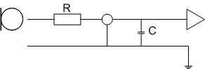
The equivalent electrical diagram is:
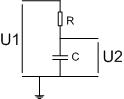
This is a low-pass filter that exactly matches the first-order passive filters (6dB/octave attenuation) which are used in baffles.
The following formula allows to calculate the necessary capacitor value for this kind of filter:
C (µF) = 159000 / Z () x f (Hz)
C is the capacitor capacity in microfarads
Z is the impedance in ohms
F is the frequency in hertz
This formula also indicates the frequency at which the signal registers a 6dB attenuation:
f = 159000 / Z x C
e.g. for a micro with a 200-ohm output impedance, use a cable with a 150 pF/m capacity.
In this case, the following formula applies:
f = 159000 / Z x C
Let f be 53000Hz
The 53000Hz frequency is the frequency at which the signal registers a 6dB attenuation.
The cable capacity is a significant parameter for high impedance circuits, such as the connection between an electric guitar and an amp. In a coaxial cable, this capacity depends on the distance separating the internal conductor and the screen. The capacity also depends on the connection length. The cable capacity has to be as small as possible and it is preferable to use relatively short connections for high impedance circuits.
1.4 Inductive effect
In alternative current, an electrical circuit inductance tends to oppose itself to any current variation.
In a straight conductor such as cables, the inductance is weak and negligible. One must take it into consideration only in the case of high frequencies.
2. Technical specifications
Indications on cable types and usage are listed on the technical specifications. We find for example:
- Its diameter in mm
This information can be useful in order to be sure that the cable fits the pin, the connector, etc.
- The number of conductors
Each cable is made up of one or several conductors.
e.g. The screen of a micro cable is not considered as a conductor by itself. We talk about x conductors + ground.
- The section of each conductor in mm²
The section of each conductor is expressed in mm².
- Number of strands per conductor
Each conductor can be made up of one or several copper strands. Generally speaking the higher the number, the thinner the strands (which compose the conductor) and the softer the cable. The skin effect also influences the number of metal strands. We will deal with this when discussing loudspeaker cables.
- Screen
The screen efficiency depends on its covering ratio compared to the internal conductors. Indeed, the shorter the potential interferences length waves, the easier they can get through small openings.
A cable can be shielded on many ways:
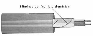
Aluminium strip screen: this kind of screen mainly fits cables for fixed installations. It offers a 100% covering and an optimal protection solution for low frequencies.
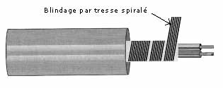
Twisted braid screen: audio cables can be shielded by a copper twist. It offers a good flexibility but a worse mechanical strength than a classical braid screen. The screen quality depends on the covering coefficient, generally mentioned in the technical specifications.
Braid screen: it is a copper braid. The quality of such a screen also depends on the covering coefficient.
- Usage temperature
It can be obvious but it is highly important to know whether a cable can resist to high temperatures or not.
e.g. to supply the socket of an halogen bulb.
- Weight per meter
It can also be self-evident but a cable of 5 x 16 mm² and a 50m-length is really heavy …
- Metric capacity between conductors
Expressed in picofarads.
- Metric capacity between a conductor and a screen
Also expressed in picofarads.
- Kilometric resistance
Cable resistance for a 1km-length, expressed in ohms.
- Impedance surge
The impedance surge is the impedance of an infinite length cable. This only applies for high frequencies. The most frequent values are 50 ohms, 75 ohms (in video) and 110 ohms (in digital signal).
According to the cable type, other features can be taken into consideration and some parameters be eluded.
3. Different cable types
There are as much cables as possible usage … Yet, they can be classified in four major categories:
- The « classical » cable
It is the cable we use for 220-volt extension cords or for loudspeaker cables. It is made up of one or several conductors coated with an insulating sleeve.
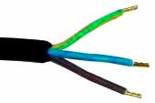
220V cable and loudspeaker cable
Depending on the cable brand and model, conductors are either numbered or differently coloured.
- Shielded and coaxial cable
A coaxial cable is a cable whose connectors are coated with a screen.
e.g cable used for micros, audio signals in general or video.

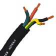
- “Side by side” cable
This cable is made up of two “side by side” cables. Each cable contains one or several conductors.

- multi-purpose cable
Lots of cable types can carry several different signals in the same insulating sleeve. Sound and electrical power, sound and video…
4. Cable by cable
As there is no versatile cable, each cable type will be studied separately.
4.1 Electrical cable
This cable type powers all our appliances. In this case, the most significant criterion is the conductor section.
We know that when the current intensity is too high, the conductor heats (Joule effect). It is thus really important to adapt the cable section according to the length and the intensity that gets through them.
Section in mm² Maximum intensity
1.5 10 amperes
2.5 16 amperes
4 25 amperes
6 32 amperes
10 40 amperes
16 63 amperes
Note : In lightning, we often use multicables (12, 18, 24 conductors…). In this case, we have several circuits while using a single main cable. Unfortunately, this cable type generally heats faster than a single cable made up of two conductors … So it is wise to set a security margin for the maximum intensity that will run through the cable. Set down a 18 x 2.5 mm² cable. For 230 volts, the maximum power reaches 3680 watts. If instead of 3500 watts, we set a maximum of 2000 watts per circuit, we have a good security margin.
4.2 The loudspeaker cable
The major role of a loudspeaker cable is to give the best connection between the amplifier and the baffles in order to dispel a minimum of energy. To do so, the conductors’ resistance must be as low as possible, in comparison to the baffle impedance.
Example:
An amplifier can provide a power of 200 watts under 4 ohms or 100 watts under 8 ohms. If we connect a 4-ohm baffle to this amplifier using a cable with the same resistance, the amplifier will have an equivalent load of 8 ohms. It will only provide 100 watts, the power being half dispelled by the cable and half dispelled by the baffle… Eventually, this baffle only receives 50 watts…
Fortunately, the actual cable resistive value is sharply inferior but this example shows the necessity to use strong section and short length cables.
Damping effect:
The cable resistance also has an influence on the damping effect.
The damping effect is the ratio between loudspeakers impedance and amplifier output impedance. This ratio provides information about the way the amplifier controls the membrane movements of a loudspeaker.
When a loudspeaker returns to its balance position it works as a current generator and no more as a receptor. This phenomenon will be stronger for low frequencies than for medium and treble loudspeakers. A damping effect of 100 for an 8-ohm load means that the amplifier output impedance is equal to 8/100, that is to say 0.08 ohms. The higher this factor, the better the amplifier-baffle connection, the amplifier will be able to “consume” the current generated by the loudspeaker. A value of 200 would be suitable, but of course it would be better to have a highly superior value.
When calculating the damping effect, add the cable resistance to the amplifier output impedance. The higher the value, the poorer the damping effect.
Once again, it is wise to use strong section and short length cables …
Which cable section to use?
With an amplifier providing 2000 watts per channel under 8 ohms, the resulting intensity would be the P/R (Power/ Resistance) square root that is to say 15,81 amperes…
In this case, a 2.5 mm² cable section is necessary, 4 mm² is even better.
Generally speaking, a 2.5 mm² perfectly fits all low and medium power baffles and a 4 mm² section is ideal for subs.
4.3 Audio cables
It’s simply a coaxial cable made up of one or several conductors coated with a screen.
This cable type can carry loop level signals as well as micro level signals.
There are several types:
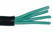
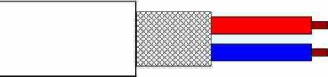
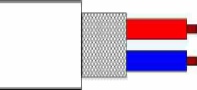
- The simple cable is made up of a screen and one or two conductors (see picture below). Cables for XLR plugs or jacks also have an external diameter of 5 or 6 mm. The cable diameter for cinch plugs or mini-jacks is much thinner.
- The side by side cable, generally used for CD players’ stereo connections, is made up of simple side by side cables.
For an unbalanced signal, the cable will be made up of a conductor and a screen. For a balanced signal, the cable will be made up of two conductors and a screen. A cable made up of two conductors and a ground could also be used for a stereo signal.
Most of the time, the section of each conductor is 0.22 mm², and of 0.14 mm² for patch cables or multipairs.
4.4 DMX cable
The DMX is a digital signal, as AES/EBU.
Can a micro cable match DMX connections? According to USITT (United States Institute for Theatre Technology)? The capacity and impedance features of an audio cable are incompatible with a digital signal. This is logical as the audio cable applies to analogical signals and DMX cable to digital signals… Yet, the impedance surge ideal value is given (between 100 and 120 ohms) for the DMX cable.
USITT reports that transmission errors can also appear when the distance exceeds 10 meters with the micro cable. It is thus essential to use an appropriate cable for a DMX signal.
5. You just have to…
... connect everything …
It is primordial to understand that each cable has its own features and that changing one of these cables is a bad idea … For example, connecting a baffle to its amp with a micro cable is a serious mistake …
Buying high quality cables (which are more expensive) is a longevity guarantee. There is nothing worse than a cable that twists upside down and that you have to throw away after two or three usage. A cable is not a string on which you can pull anyhow…
Have fun!
Bibliography
- Circuits électriques, Courant alternatif, Herbert W. Jackson, Editions Dunod, 1988
- Circuits électriques, Courant continu, Herbert W. Jackson, Editions Dunod, 1988
- Condensé de physique, Jean- François Lambert, Editions MPC, 1996
- Le son live, Paul White, Editions Eyrolles, 2001
- Electricité pratique, J.-M Fouchet, Editions Dunod, 1999
| Moteur de recherche |
| Plan du site |
| Son |
| Eclairage |
| Electricité |
| Câblage et connectique |
| Bien débuter |
| Acoustique |
| Line Array - Ligne source |
| Impédance - HP |
| Décibels |
| DI Box |
| Adaptation d'impédance |
| Symétrique - Asymétrique |
| Lignes 100 volts |
| Consoles |
| Acoustique fondamentale |
| Timbre |
| Phase: Première partie |
| Directivité des basses fréquences |
| End fire |
| End Fire 2 |
| Sources sonores - propagation |
| WST |
| Circuits auxiliaires |
| INSERTS |
| Groupes |
| Bouchon DMX |
| Câbles multipaires électriques |
| Electricité - Notions élémentaires |
| Tableaux électriques |
| L'électricité pour nos spectacles |
| Multimètres - Utilisation |
| Indices de protection (IP) |
| Branchements |
| Relier les enceintes |
| Les types de câbles |
| Câbles électriques |
| Réaliser ses adaptateurs |
| Connecter un clavier |
| Série et parallèle |